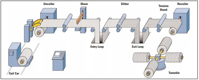
On metal slitting lines, blade life comes down to two things: the material the blade is made from, and how precisely it is installed. Most customers who report rapid wear or frequent breakage are dealing with an installation problem — not a blade quality problem.
SUREAY is sharing three installation tips that apply to any metal slitting line. Follow all three and you can realistically extend the service life of your rotary shear blades by 30% or more.
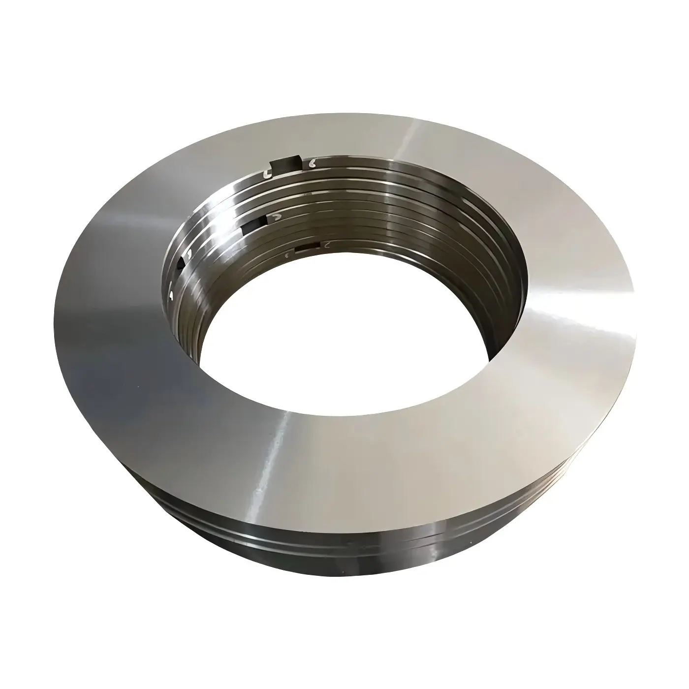
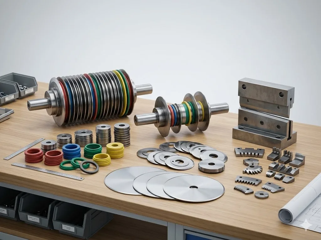
Tip 1: Set the Correct Axial Clearance
Axial clearance — the gap between the two mating rotary shear blades — is the single most influential installation parameter. Set it wrong and the blades will fail regardless of steel grade or surface treatment.
The most common mistakes are adjusting clearance by feel or using a single fixed value across all material thicknesses. The correct approach is to calculate clearance as a percentage of sheet thickness — typically 8–12% — and verify it with a feeler gauge or dial indicator at multiple points along the cutter shaft.
| Material Thickness | Recommended Clearance |
|---|---|
| ≤ 1.5 mm (thin plate) | 0.03 – 0.08 mm |
| 1.5 – 4 mm (medium plate) | 0.08 – 0.15 mm |
| > 4 mm (thick plate) | 0.15 – 0.25 mm |
If clearance is too small, frictional heat builds at the blade face and the cutting edge chips. If clearance is too large, the slit edge becomes rough, burr height increases, and the blade dulls rapidly under the bending load.
Tip 2: Verify Cutter Shaft Parallelism
If the upper and lower cutter shafts are not parallel, the effective clearance varies across the cut width. One side of the blade set is underloaded while the other is overloaded — causing uneven wear, accelerated edge damage, and inconsistent slit width.
Before installing the blades, measure the cutter shafts directly. Check runout at both ends of each shaft — error must be within 0.02 mm. Then verify shaft-to-shaft parallelism across the full working length using a dial indicator and straight edge — error must be within 0.05 mm total.
Bearing wear and frame deformation accumulate over time and shift shaft geometry. Repeat this check every six months as part of a scheduled preventive maintenance cycle.
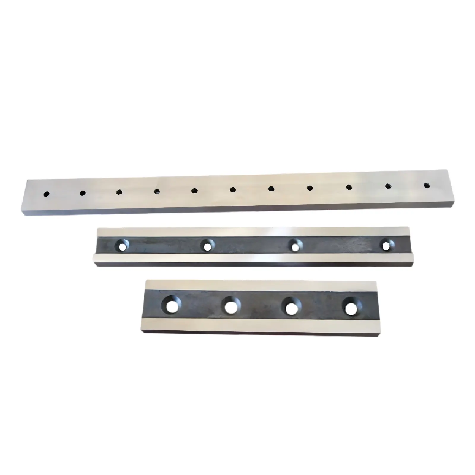
Tip 3: Apply the Correct Bolt Torque
Under-tightened blades micro-shift during rotation. Even a few microns of movement per cycle generates fretting wear at the mounting face and introduces runout that transfers to the cutting edge. Many failures attributed to blade brittleness are in fact caused by mounting instability.
Use a calibrated torque wrench and apply the specified torque in two or three progressive steps. Ensure blade and shaft mating surfaces are clean — free of oil, burrs, and debris — before assembly. Use non-woven fabric and alcohol for the final wipe.
| Bolt Size | Required Torque |
|---|---|
| M12 | 70 – 90 N·m |
| M16 | 150 – 180 N·m |
| M20 | 250 – 300 N·m |
Installation Checklist
| Check Item | Specification | Method |
|---|---|---|
| Axial clearance | 8–12% of material thickness | Feeler gauge or dial indicator |
| Cutter shaft runout | < 0.02 mm | Dial indicator |
| Cutter shaft parallelism | < 0.05 mm (full length) | Dial indicator + straight edge |
| Bolt torque (M12 / M16 / M20) | 70–90 / 150–180 / 250–300 N·m | Torque wrench |
| Blade & shaft surface | No oil stains, no burrs | Non-woven fabric + alcohol |
Technical Note
Correct installation outperforms expensive blades every time. If your blades are wearing out quickly, start here — not with the blade specification sheet.
Need Help With Your Slitting Line?
If you are having problems with your metal slitting line, send us your drawings or photos and our engineers will give you a free technical assessment. SUREAY specialises in precision rotary shear blades and metal coil slitting knives for all major slitting line brands.
Visit www.sureay.com · Email lynn@sureay.com · Call +86 180 0555 0657 · Connect on LinkedIn or Facebook