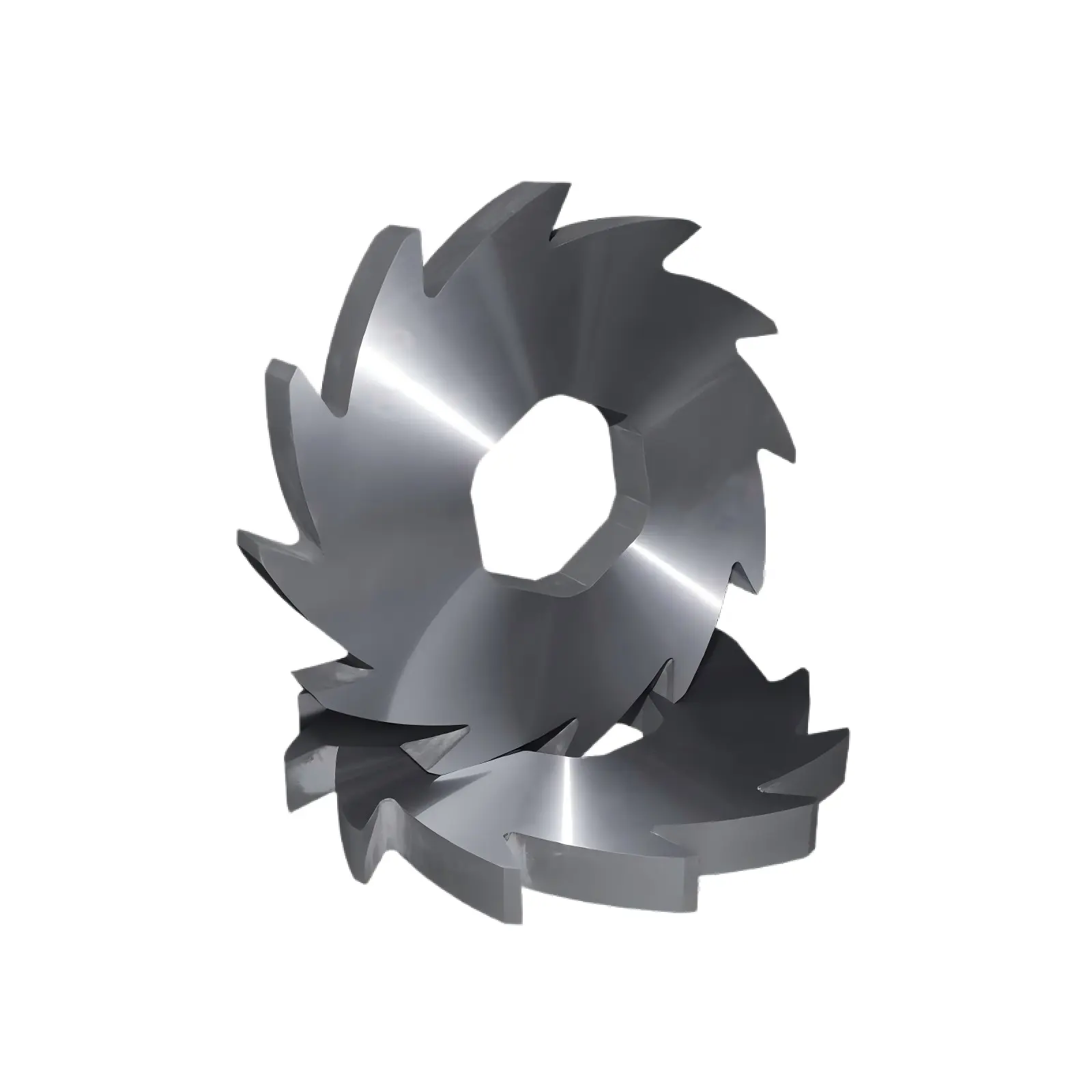
In recycling and waste processing, shredders are often among the highest electricity consumers on the line. Operators usually look first at motor power, hydraulic pressure, or screen size, but the twin shaft shredder blade arrangement has a direct influence on how smoothly the machine bites, shears, and discharges material.
Blade spacing, hook timing, spacer width, and shaft overlap determine whether cutting load is distributed in a stable sequence or concentrated into repeated impact peaks. A well-arranged stack helps lower kWh per ton, reduce reverse cycles, and improve wear balance across the full cutter set.
Why Blade Arrangement Changes Power Consumption
A shredder does not consume energy only when it cuts. It also consumes energy when the rotor pulls material into the chamber, compresses oversized feed, clears partially cut pieces, and overcomes friction between blades, spacers, shafts, and the material itself. Arrangement influences all of these energy paths.
| Arrangement Factor | What It Changes | Energy Effect |
|---|---|---|
| Blade spacing | Material bite and discharge path | Too wide causes impact peaks; too tight increases friction |
| Tooth timing | Whether teeth hit together or in sequence | Sequenced engagement smooths torque demand |
| Spacer width | Compression and material release | Incorrect width raises blockage risk and wasted load |
| Overlap / clearance | Shearing efficiency and side contact | Poor settings convert motor load into heat instead of cutting |
When these factors are controlled, the motor runs in a steadier load band. When they are not, the machine shows current spikes, unstable throughput, frequent reversals, and localized blade damage.
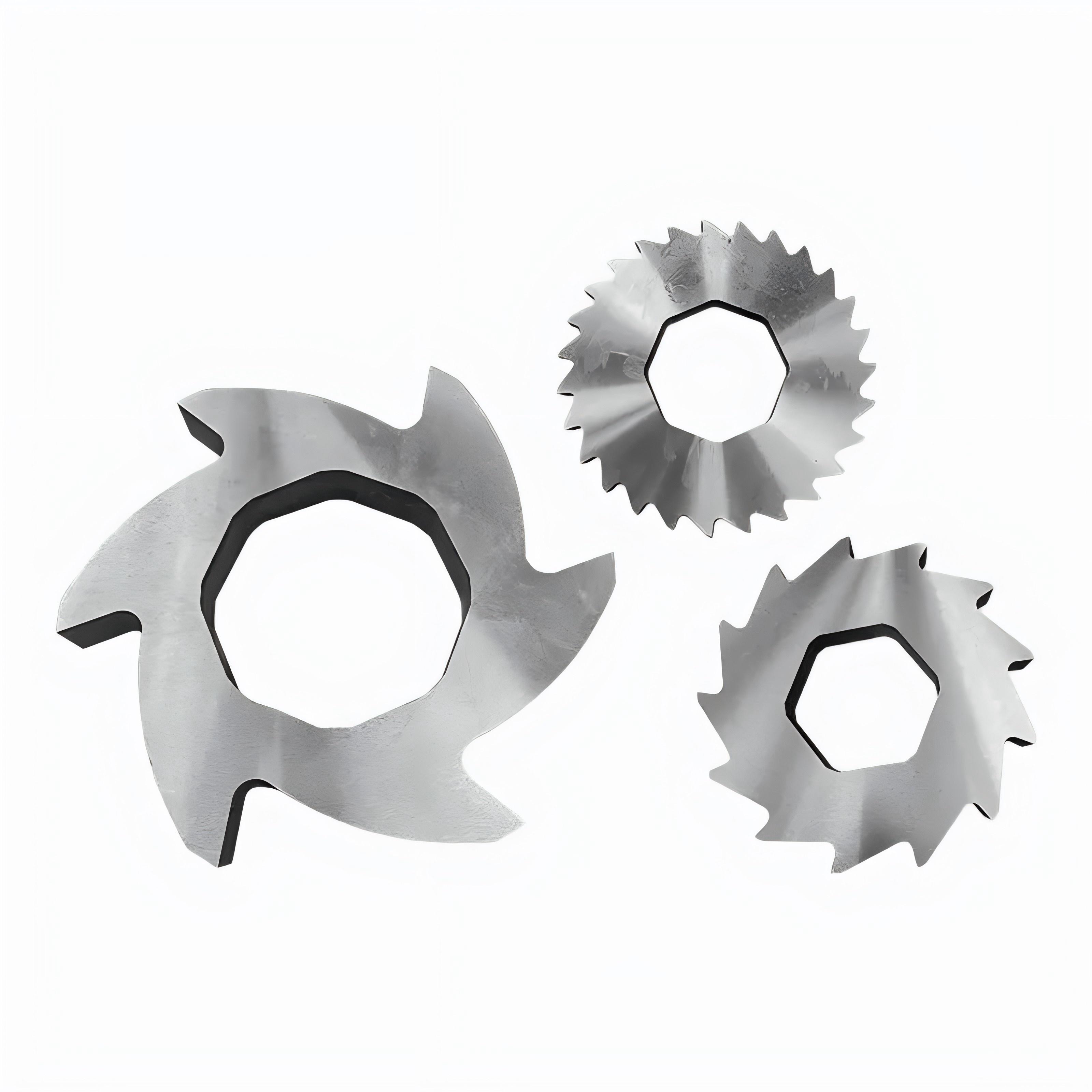
For operators evaluating shredder blades and cutter inserts, arrangement should be reviewed as a system question rather than a single-disc question. Blade thickness, hook profile, spacer stack, shaft timing, and heat treatment all work together.
Common Arrangement Types and Their Energy Behavior
| Arrangement Type | Cutting Behavior | Energy Impact | Best Fit |
|---|---|---|---|
| Wide spacing / large clearance | Strong bite but intermittent cutting | Higher torque peaks and repeated impact risk | Bulky material that needs aggressive grabbing |
| Dense straight stack | More continuous contact | Stable when feed is smooth, but friction rises if too tight | Thin plastic, film bundles, light waste |
| Staggered arrangement | Adjacent teeth cut in sequence | Lower load fluctuation and smoother motor demand | General plastic recycling and mixed waste |
| Helical arrangement | Teeth engage in a spiral progression | Smoothest transition and lower vibration in suitable lines | Continuous recycling lines targeting steady throughput |
The correct layout depends on material shape, toughness, bulk density, feed method, and target output size. The densest stack is not automatically the best choice if it creates unnecessary side friction or wrapping.
How Blade Gap Influences Torque, Blockage, and Friction
Excessive Gap
When blade gap is too large, the stack may fail to grab material cleanly. Instead of controlled shearing, the machine repeatedly bends, impacts, and drags the feedstock. The result is unstable torque demand, poor bite, and more overload or reverse events.
This condition is common when an open blade stack is used for film, hollow containers, low-density waste, or other feed that needs guided engagement rather than blunt impact.
Insufficient Gap
When the gap is too small, the material becomes over-compressed between adjacent discs. In that case, a larger share of the motor load is spent on rubbing and heat generation rather than useful cutting work. Operators often see higher chamber temperature, sticky residue, side wear, and elevated current even at partial load.
Engineering Note
Both excessive and insufficient gap can increase energy consumption. The difference is where the energy is lost: impact and repeated reversal on one side, or friction and heat on the other.
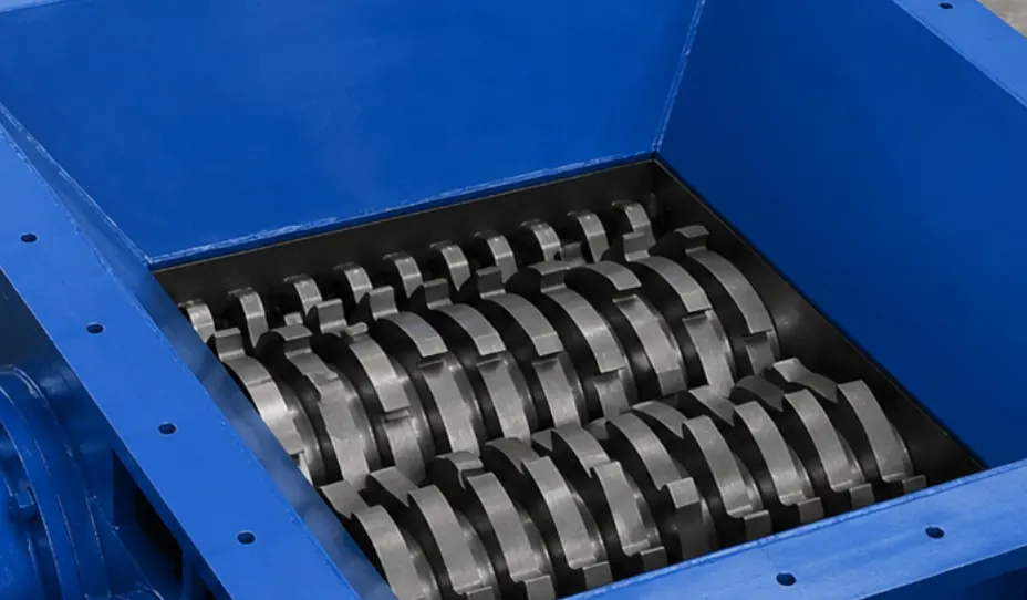
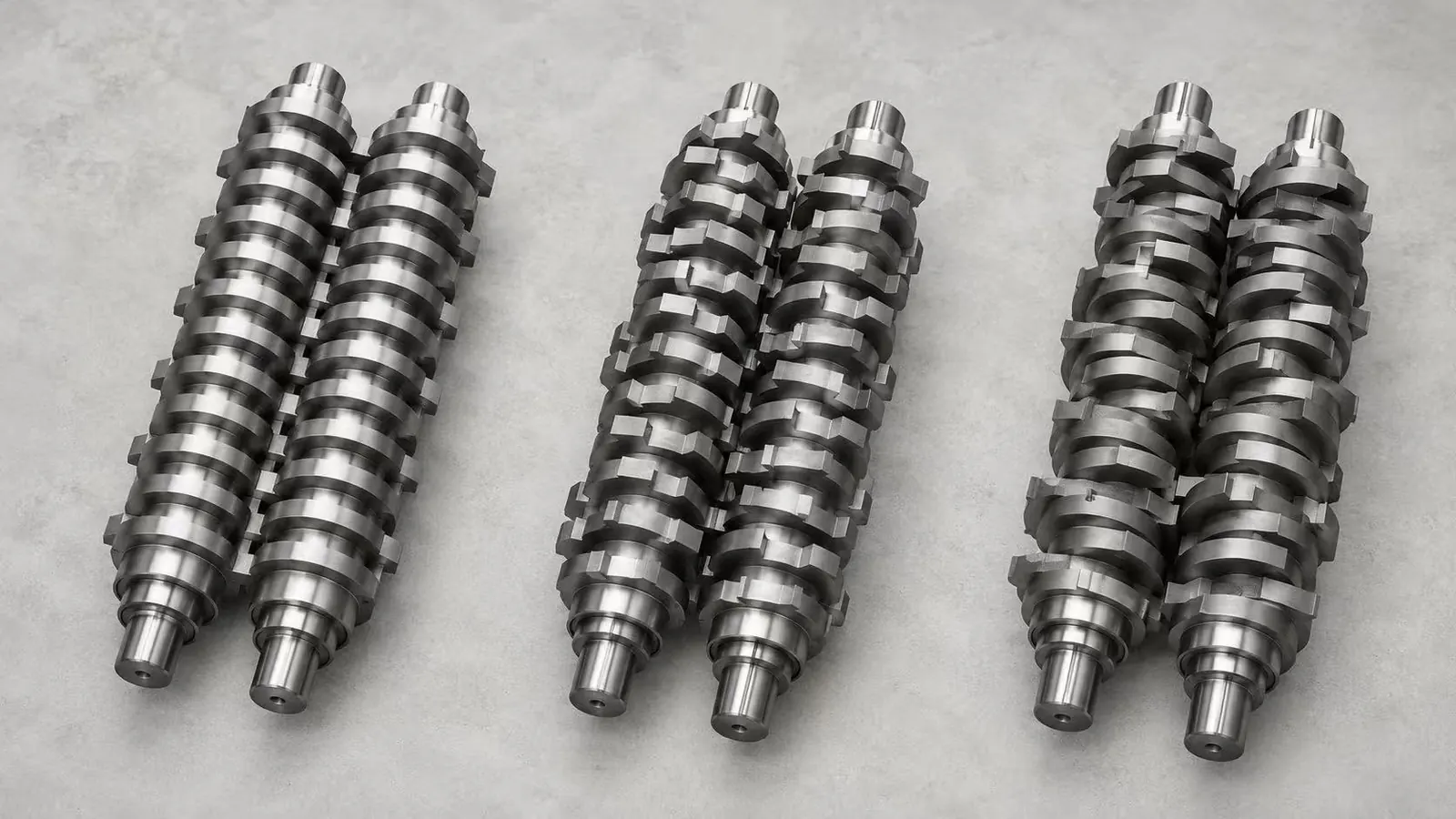
Staggered vs Helical Arrangement
In a staggered arrangement, adjacent teeth are offset so multiple hooks do not strike the material at the same instant. This usually reduces sudden torque peaks and helps the motor stay closer to an efficient operating band.
In a helical arrangement, tooth positions progress along the shaft in a spiral sequence. For suitable feedstocks, this produces smoother chamber loading, lower vibration, and more consistent discharge. However, helical layouts still need sufficient bite force, shaft strength, and blade toughness for thick or contaminated material streams.
| Blade Arrangement | Relative Energy Use | Torque Stability | Wear Pattern |
|---|---|---|---|
| Wide spacing / large clearance | High | Unstable | Local impact wear |
| Dense straight stack | Medium | Moderate | Possible side wear |
| Staggered arrangement | Lower | Stable | More even wear |
| Helical arrangement | Lower in suitable conditions | Very stable | Predictable wear distribution |
Field comparisons often show lower kWh per ton when tooth engagement is sequenced more smoothly, but the exact gain depends on feedstock, shaft speed, feed consistency, blade geometry, and how the measurement is taken. The practical lesson is straightforward: smoother engagement usually means less wasted energy.
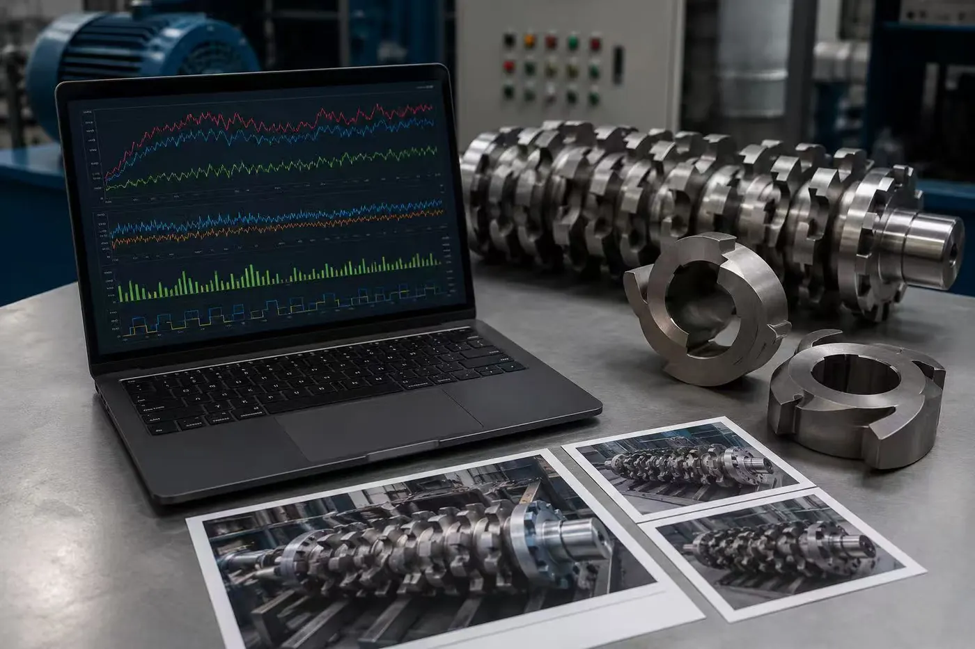
How to Diagnose an Existing Blade Stack
Before replacing the whole machine, inspect the blade shaft as a system. Many energy problems can be diagnosed from spacer arrangement, tooth timing, and the location of wear or chipping. This is especially important on recycling lines processing variable feedstocks such as rigid plastics, film, light metal scrap, or battery modules.
| Check Item | What It Reveals |
|---|---|
| Blade spacing | Whether the material is being bitten cleanly or over-compressed |
| Tooth timing | Whether the cutting load arrives as impact peaks or smooth sequence |
| Edge wear pattern | Whether the load is distributed evenly across the stack |
| Side wear | Whether friction is consuming unnecessary energy |
| Current curve and reverse cycles | Whether blockage or torque spikes are being triggered by the shaft layout |
| Output size variation | Whether cutting remains consistent across the chamber width |
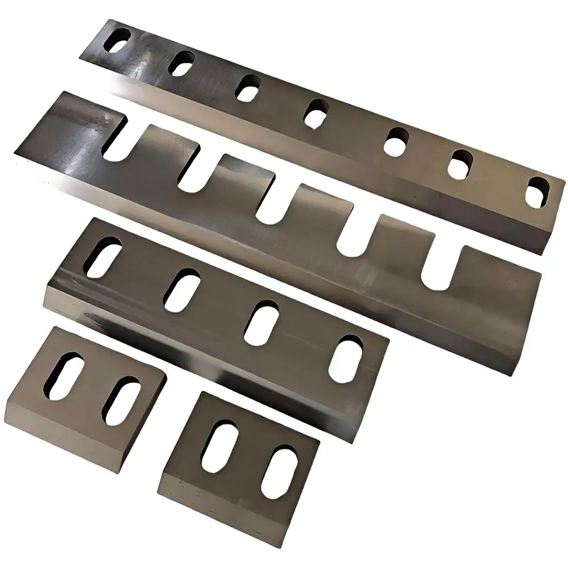
Useful input data includes material type, feed size, target output size, motor power, shaft speed, blade diameter, blade thickness, spacer width, and photos of worn edges. With that information, a blade manufacturer can judge whether the root cause is spacing, tooth profile, blade material, heat treatment, or general machine condition.
Recommended Priorities by Material Type
| Material | Main Challenge | Arrangement Priority |
|---|---|---|
| Plastic film | Low density, wrapping, poor bite | Controlled tooth engagement and anti-wrapping layout |
| PET bottles | Hollow shape and bouncing feed | Staggered or helical engagement for stable pulling |
| Rigid plastic | Higher cutting force | Balanced spacing with strong hook geometry |
| Light metal scrap | Impact load and edge chipping | Controlled clearance with tougher blade material |
| Battery recycling | Mixed hard layers and safety-sensitive processing | Application-specific shaft layout and high-toughness tooling |
If your line handles multiple streams, select the arrangement around the most difficult material rather than the easiest one. For example, a stack suitable for thin film may not remain efficient when the same line starts processing housings, runners, or battery pack scrap. In those cases, compare the cutter layout against your plastic recycling blades, battery recycling blades, and downstream granulation requirements such as granulator blades.
When a Redesign Is Worth Considering
A blade stack redesign is worth reviewing when energy consumption per ton keeps rising, reverse cycles become frequent, output size remains inconsistent, operators have to reduce feed rate to avoid overload, or teeth chip in the same position repeatedly. Replacing blades with the same arrangement may only repeat the same failure mode.
Sureay manufactures matched shredder blade and spacer sets for recycling applications, including twin shaft recycling blades and application-specific tooling for plastic, metal, tire, and battery waste. Reviewing arrangement together with material grade and heat treatment usually produces a better result than changing only one variable.
Technical Note
Need help diagnosing a shredder blade shaft? Send blade dimensions, spacer width, motor power, material type, output target, and photos of the worn stack. Sureay engineers can review whether the current arrangement is increasing energy consumption or shortening blade life.